Basic Mobile Phone Hardware Repair and Troubleshooting Techniques
Introduction
Hardware repair in mobile phones is often more challenging and time-consuming than software troubleshooting. Unlike software issues, which can often be resolved without opening the device, hardware repair requires dismantling the phone and inspecting its internal components.
Mobile phone technicians are usually divided into two specialties: hardware experts and software experts. Some highly experienced technicians master both, gaining the ability to repair any issue and often earning higher income due to their versatile skills.
Step-by-Step Hardware Troubleshooting Procedure
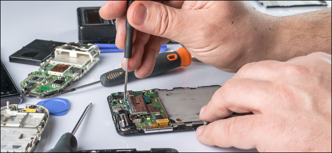
1. Visualization Check
Before touching any internal components, carefully examine the handset. Look for visible damage such as dust, corrosion, broken components, or bent parts on the printed circuit board (PCB). This helps determine whether the device is repairable.
2. Gather Phone History
Ask the customer about the phone’s history, including incidents like liquid exposure, drops, or physical impacts. Understanding the phone’s background helps prioritize which areas to inspect first.
3. Software Check
Use a flashing device compatible with the phone to read logs or check the firmware. Logs can indicate which lines or components may be faulty. If software issues are found, attempt reformatting or flashing first. If problems persist, proceed to hardware troubleshooting.
4. Circuit Analysis
After dismantling, carefully analyze the PCB and its components. Take note of how circuits are mounted, connected, and assembled. Formulate a step-by-step plan before testing components.
Example: Troubleshooting a Faulty Microphone on a Nokia 6300
Step 1: Locate the Microphone Circuit
Refer to the schematic diagram to identify the microphone circuit and map all component locations. Knowing where each connection goes is critical for accurate testing.
Step 2: Check for Short Circuits
Use an analog multimeter set to x1 resistance. Connect the probes to the microphone terminal pads (inner and outer layers). A short circuit is indicated by readings close to zero ohms.
Step 3: Trace Component Lines
Follow the paths from the microphone terminals to the nearest components, such as coil filters. Test across each coil terminal to ensure there are no breaks or faults in the circuit.
Step 4: Test Open Paths and Capacitors
Identify lines that can be probed, such as those passing through filter capacitors or coils. Measure the resistance along these paths to confirm connectivity.
Step 5: Check Resistors
For resistor lines that connect to ICs (like the Retu IC), measure the resistance values directly. This helps verify whether resistors are functioning correctly.
Step 6: Inspect EMI Filter
If all previous components are working properly, the EMI filter may be faulty. Remove it from the PCB and test the lines between the microphone terminals and the EMI filter connections.
Step 7: Evaluate the IC
Refer to the schematic diagram to check IC connections. If uncertain about the internal circuitry, replacing the IC with a known good unit is often safer.
Step 8: Final Step – Power Management / Audio Codec IC
If all lines and components are functional, the issue may be within the power management or audio codec IC. Reworking the IC by reheating can sometimes fix connectivity issues. While doing this, check all terminal balls and line connections to ensure the microphone is properly linked to the circuit.
Conclusion
This method provides a systematic approach to basic mobile phone hardware troubleshooting. By following these steps—visual inspection, software check, circuit analysis, and component testing—you can identify and repair faulty components effectively. Advanced techniques, such as IC reworking, should be performed carefully or with guidance as experience grows.
Post a Comment